TNI Architects Inc. (TNI) offers architectural drawings including CAD-based plans, diagrams, and schematics that provide detailed information about buildings. These technical drawings are created during the early planning stages of construction projects.
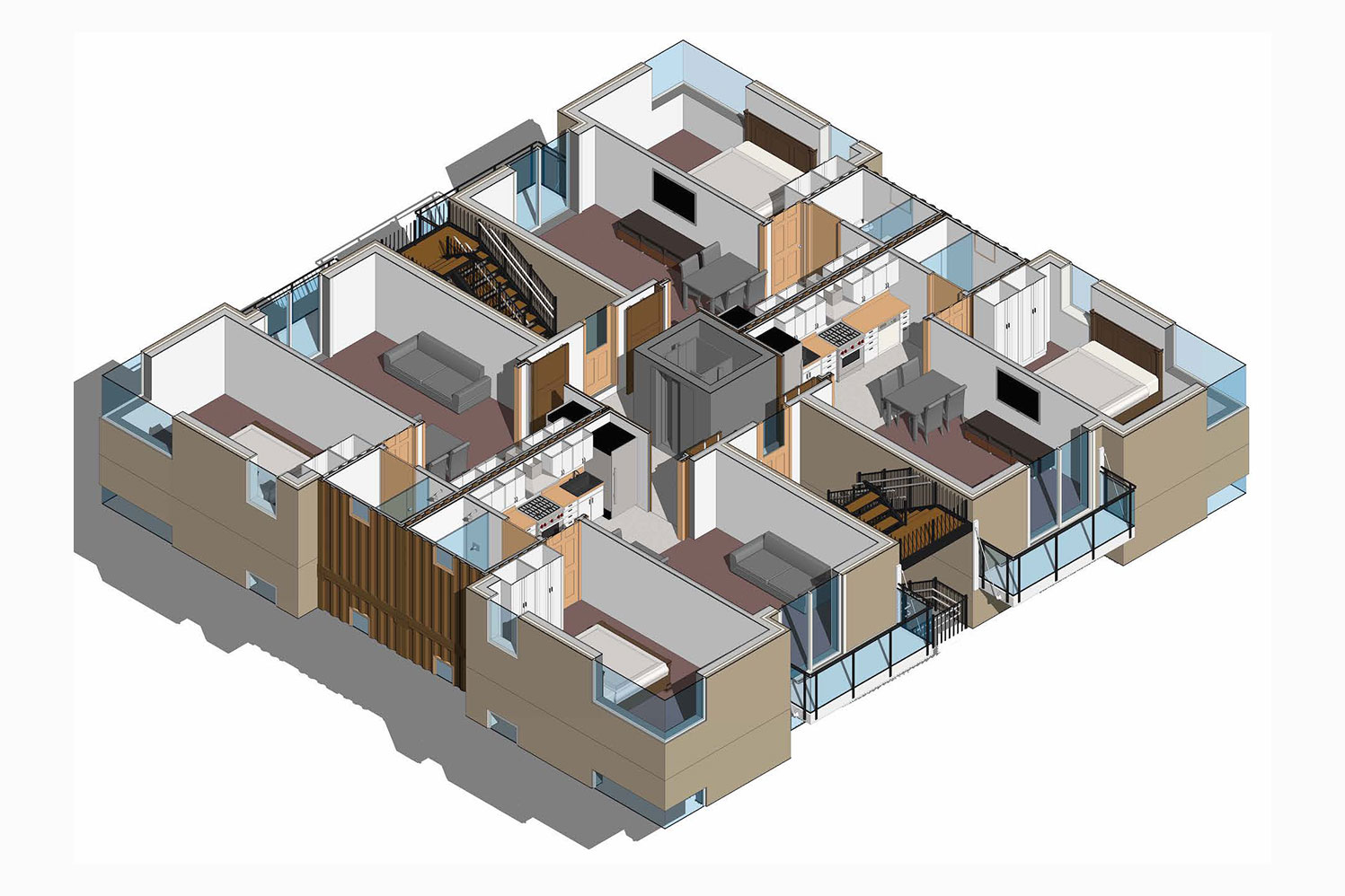
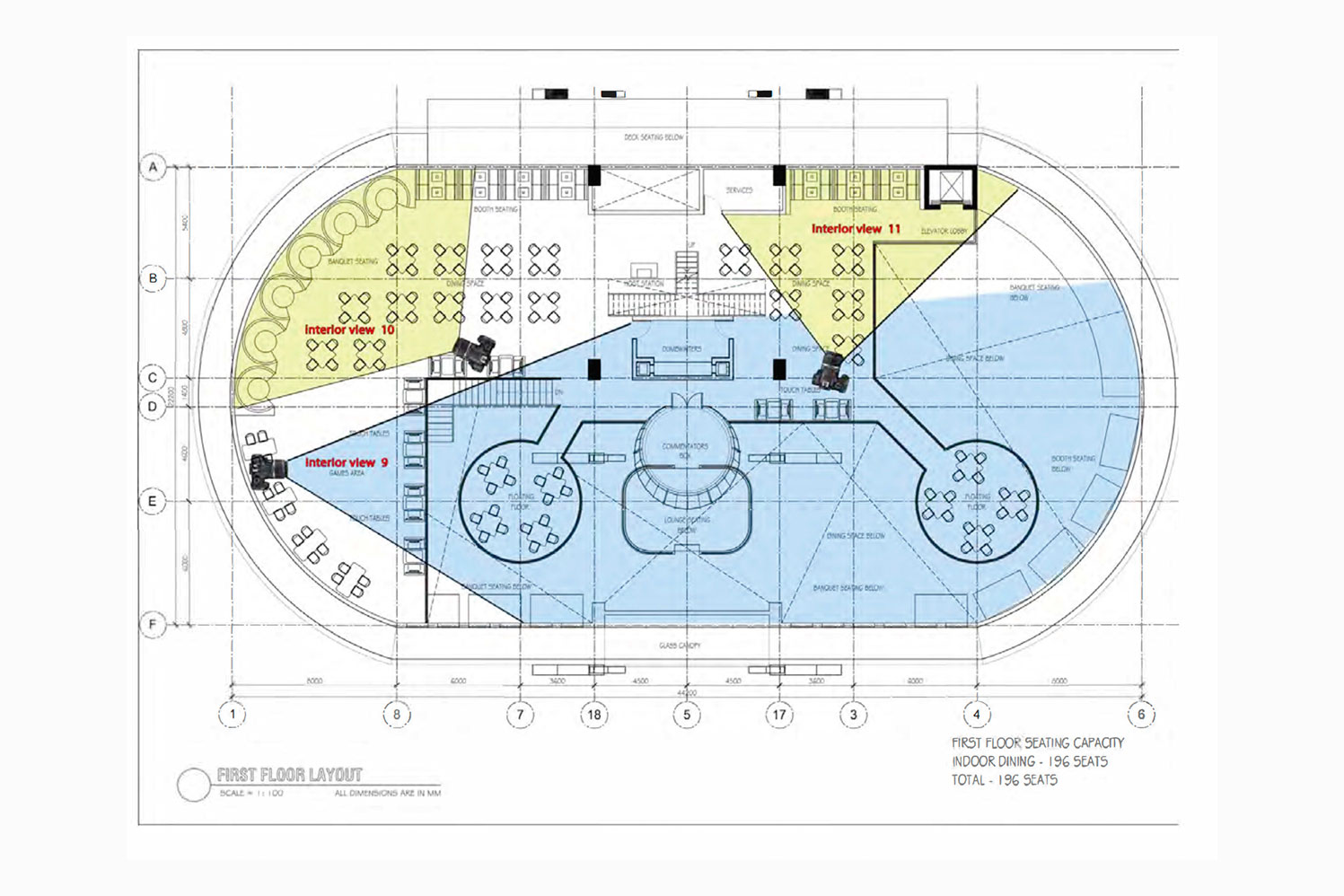
A typical plan set includes (but is not limited to):1. Floor plan: This fundamental architectural diagram offers a top-down view to showcase the spatial arrangement within a building. It shows walls, windows, door openings, and other features at a specific level. Additionally, it may include the floor, stairs (up to the plan level), fittings, and occasional furniture. Objects above the plan level, such as overhead beams, are typically represented as dashed lines.
2. Site plan: This plan provides an overview of the entire project scope, displaying property boundaries, access points, nearby structures if relevant, and existing/proposed buildings. It may also feature roads, parking lots, footpaths, landscaping, trees, and utilities such as drainage, water supply, electrical, and communication lines. Site plans are commonly used to make decisions regarding site layout, building size, and orientation. They are crucial for compliance with local development codes, including historical site restrictions.
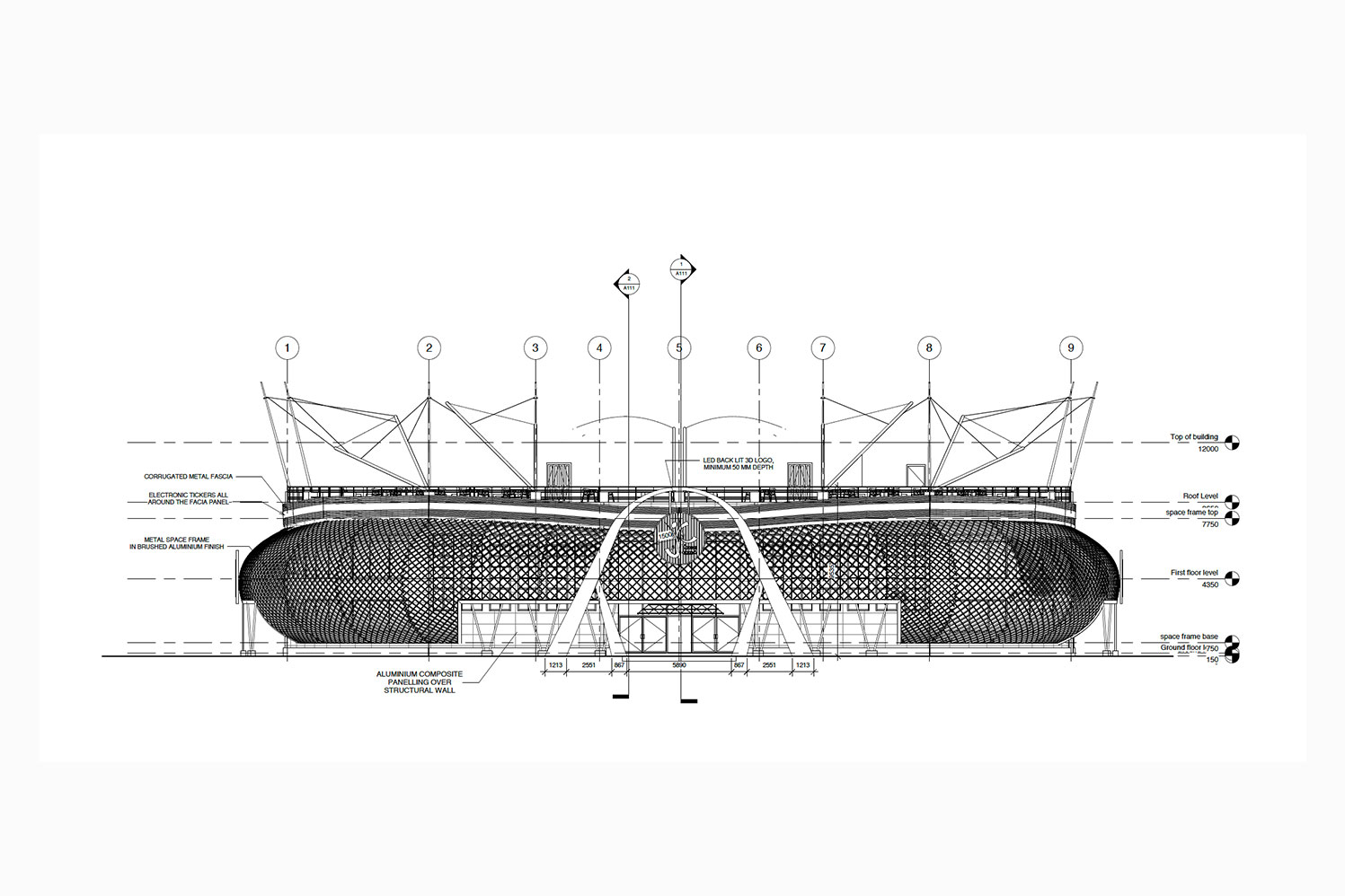
3. Elevation: An elevation is a view of a building from one side, representing a flat façade. It is the most common way of depicting the external appearance of a building, labeled based on the direction it faces. For example, the southern elevation of a building can be seen when looking toward the north. As buildings rarely have a simple rectangular shape, an elevation typically displays all visible parts from a specific angle. Geometrically, an elevation is a horizontal orthographic projection of a building onto a vertical plane, usually parallel to one side of the building. Architects often use the term elevation interchangeably with façade, so the "north elevation," for instance, refers to the north-facing wall.
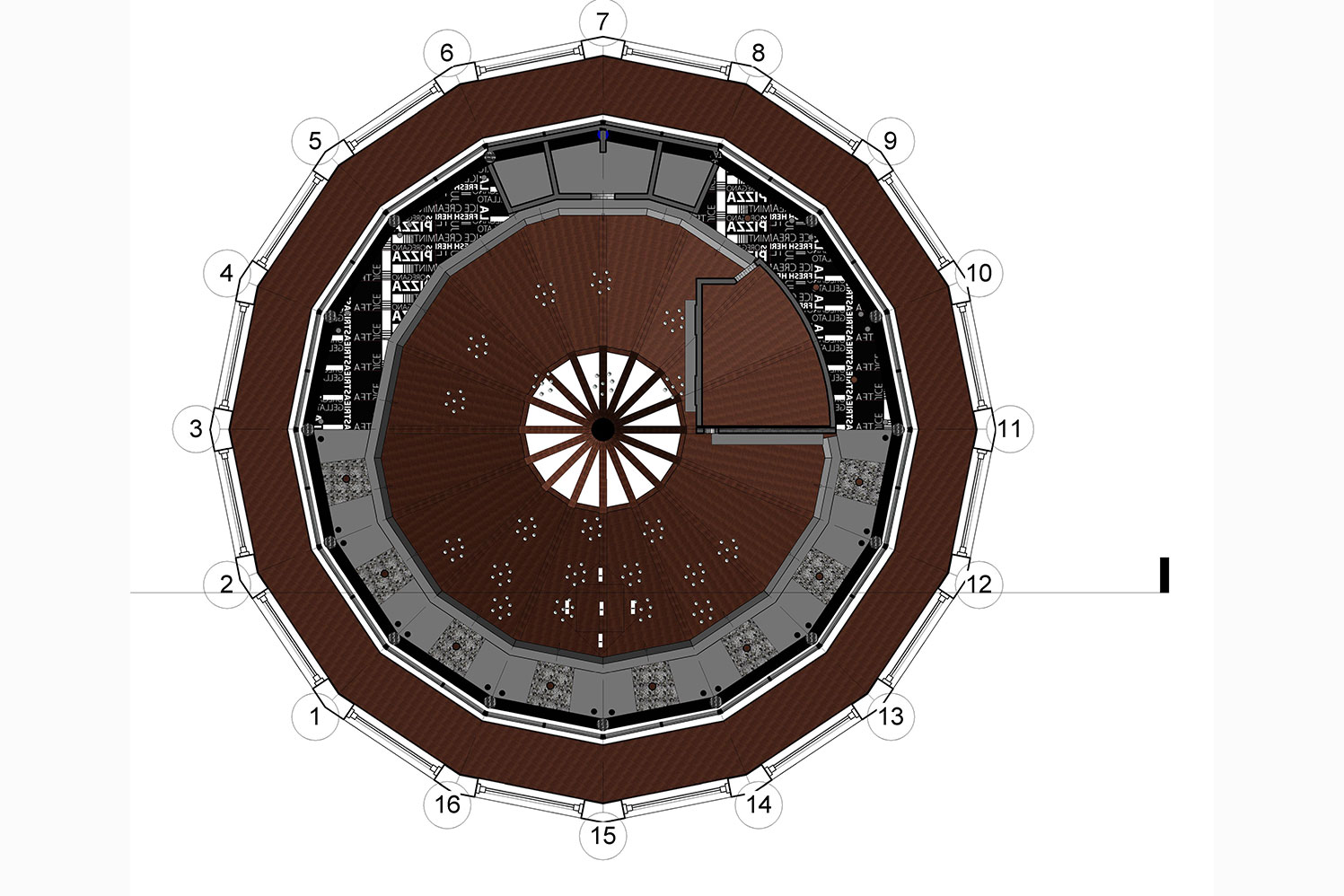
4. Reflective Ceiling Plan (RCP). A reflected ceiling plan (RCP) is a detailed print that showcases the dimensions, materials, and other pertinent information regarding the ceiling in each room depicted on your blueprint. The term "reflected" is derived from the concept of looking down at the ceiling as if there were a mirror on the floor reflecting its plan back to you. Architects and builders utilize this method of drawing RCPs to ensure that the orientation of the floor plan matches that of the ceiling plan, making it easier to comprehend. Essentially, you are presented with a top-down view of both the ceiling and the floor.
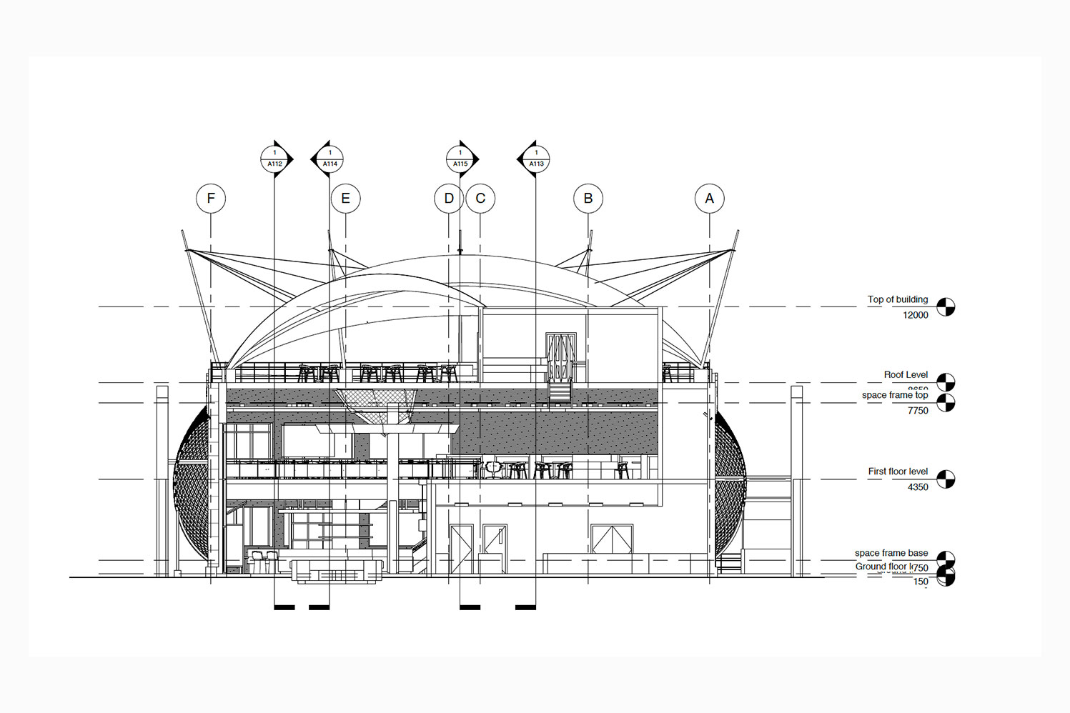
5. Cross Section: A cross section, sometimes called a section, illustrates a vertical plane cutting through an object, similar to how a floor plan shows a horizontal section from the top. In a section view, the objects intersected by the section plane are portrayed as bold lines, often filled in to represent objects that are cut through. Objects beyond the section plane are generally shown as thinner lines. Sections are useful for describing the relationship between different levels of a building. In the provided illustration of the Observatorium, the section reveals the external dome, an interior dome only visible from inside the building, and how the space between accommodates a large astronomical telescope. These relationships may be challenging to comprehend through plans alone. A sectional elevation combines a cross section with elevations of other building parts visible beyond the section plane. Geometrically, a cross section is a horizontal orthographic projection of a building onto a vertical plane, with the vertical plane cutting through the building.
6. Detail drawings: Detail Drawings provide an in-depth view of specific construction elements at a larger scale, illustrating how the components fit together. They also highlight intricate surface details, such as decorative elements. Section drawings, at a larger scale, are commonly used to depict complex junctions in building construction, such as floor-to-wall connections, window openings, and roof structures. A comprehensive set of construction details encompasses both plan details and vertical section details, allowing for a three-dimensional understanding of the construction. Detail drawings are typically represented at scales of 1/10, 1/5, or full size.